Last Updated on 16th November 2023 by nightowl
Note: As can be seen from the comments below, this information seems to also applies to WO FLT132 IV.
A while back I purchased a William Optics Fluorostar FLT 91 Telescope as on paper the specs seemed to be exactly what I was looking for. This particular scope was also supposed to be checked and tuned. Initially everything did feel okay but it didn’t take long for me to start noticing some issues with the focuser. Right out of the box it had some “rough spots” on the length of the travel. A little bit of grease on the rack and pinion system took care of that.
With visual observations everything seemed to be okay with a 2” diagonal and some 1.25” eyepieces. It wasn’t until I swapped to my imaging setup when the more annoying issues started to show up. The setup was a HoTech SCA Field Flattener + 5×2” slot EFW + Atik 383L+ spacers. This was a lot more weight hanging off the focuser than I had with the visual setup.
First I noticed a slight horizontal play when I gave it a little wiggle as soon as the focuser was racked out even a little bit. Vertically it felt okay. Or so I thought. Quick email to WO and I was told to adjust the focuser tension using these two screws:
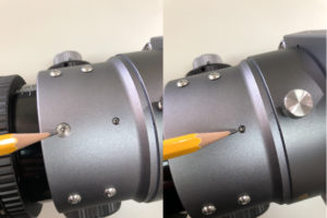
For several nights I kept adjusting the focuser tension and every time I thought I got it good the focuser was too stiff to operate. Not good. Also the screw in the second photo above didn’t seem to do much even if I tightened it a tad more than I was comfortable with. It seemed to be more about the bigger screw and the tension of the pinion assembly at the opposite side. While doing all this I noticed another issue with the focuser. It seemed to tilt up and down depending which way you turn the focus knobs. I thought this can’t be right on a £2k scope…
Eventually I decided to take the focuser apart and really see how it’s been built and why I can’t adjust it properly. To do this, first remove the whole focuser rotator assembly which just unscrews anti-clockwise.
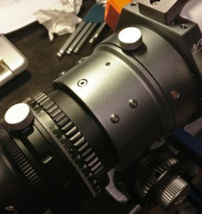

Next step is to remove the focuser knob assembly which is held in place with the two socket head bolts in the middle. You might want to loosen up the four small grub screws first that are stabilising the assembly against the focuser body as they’ll need to be adjusted upon re-assembly again.
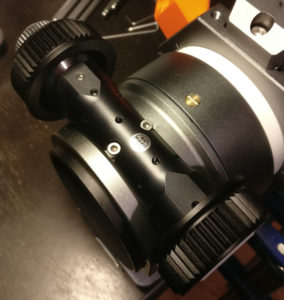
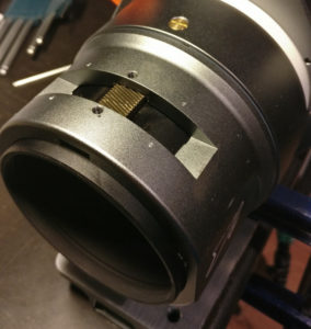
Finally to remove the focuser body you’ll need to remove the three brass screws and the thumb screw around it (On the table next to the red screwdriver below).
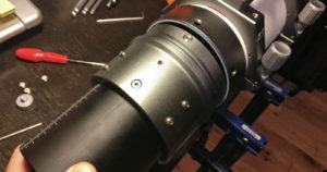
And whaddaya know… This reveals another tension adjustment screw at the front of the focuser body. Why they have decided to hide this inside the scope with no access from the outside is beyond me. Seems like a bit of a design flaw… I am tempted to drill a small hole on the top of the body just big enough so I can adjust the screw with an allen key without dismantling everything again. This screw was rather loose on my scope and caused all the troubles I mentioned above.
It is now possible to push the focuser tube through the body so that the teflon sliders inside can be inspected. Looking at it from the inside I really don’t think the second screw in the first photo in this document can be used to adjust the tension as advised by WO. I think it’s there just to stop the plastic tension bar sliding out the assembly. The tension is adjusted using the two bigger similar looking screws at the front and back of the body. Using these I was able to have a tight fit without any play even with the pinion assembly removed while still being able to move the tube in and out without too much effort.
With all this done it was time to put it back together again which is basically just the reverse of disassembly. Care must be taken not to overtighten anything. Special care must be taken with the three brass screws and the thumb screw holding the focuser body to the telescope as they have plastic tips on them pressing against the groove on the metal. They need to be snug but don’t go too crazy with them.
When re-installing the pinion assembly start by tightening the two socket head bolts just tight enough so the focuser knobs feel nice and smooth. Then snug up the four small grub screws to prevent it from moving about. Hope this helps!
I’m glad I found this. I have similar issues with my GT-71 focuser. Now the fall (winter + spring) rains are starting I will have some downtime to do some disassembly and adjustments.
(and build the ESP dew heater controller…new boards should be here this week)
Cheers
Hi David. Thanks for the comment. I have no experience on the GT-71. Do let us know if the mechanics are same/similar and the information here apply? Clear skies!
Glad you sorted the problem out. Did you report your efforts back to W.O. and did you get any response? I’m looking at getting a longer focal length scope to go with my GT-81 and am surprised at what you found.
Thanks for your comment. Yes I was very surprised myself too. No I didn’t feed this back to W.O. Maybe I should…
Just wanted to say this was very helpful. Got a new FLT 132 IV with the newer 3.7″ focuser. I had to add about 75mm of extension to the end of the tube so that a filter wheel and cooled ASI2600MC could come to focus. The scope came to focus at about the 46mm marking on the tube. As like you, I could move the tube horizontally quite a bit with just a little bit of force even at the middle of extension. The FLT 132 IV focuser can be disassembled as in your document-very similar. My focuser has the front and back adjustment screws just like yours. The front adjustment is also hidden like yours. The focusing tube had a lot of play inside of the focuser. Both the front and back adjustment screws needed to be screwed down to eliminate the slop. The problem was that the adjustment screws were cemented. I needed to find a flat screwdriver bit that fit the slot tightly so that I could break the screw loose. The front screw was easy to break loose but the back screw was tight and with a rather loud crack, it broke loose. With the focuser mechanism removed, I adjusted the two screws so that the tube slid on the teflon without binding. I put a couple drops of blue screw locking cement on the adjustment screws to hold them in place but still be able to adjust them later. I also adjusted the four set screws so that the focuser mechanism pinion gear did not rock over the rack. Everything came back together and works great with very little wiggle now. I also had that sinking feeling that I spent big bucks on the scope and the huge 3.7″ focuser was all wiggly. Thanks again for putting this together. I feel so much better now that the focuser is solid.
Glad you got your’s sorted out too! Good to know that this info applies to the FLT132 IV as well. Thanks for posting.
Great tutorial, perhaps you could teach William Optics Quality Control a thing or two…… my FLT91 was suffering from focuser malfunction, using your excellent & concise tutorial gave me the confidence to tackle the issue & I might add corrected my focuser problems. I notice William Optics have addressed the issue by providing an image in the updated FLT Manual on focuser adjustments. Although it does not provide the information on how to access hidden tension grub screw, which in your case & mine was the issue. Great work.
Very good tutorial!! Before I received mine, I was also full of fears of focuser problems, however everything worked fine.
And I have a query that I imagine you can help me. I just bought the Zwo EAF, it hasn’t arrived yet, but I have my doubts as to which pair of screws/holes I should adjust the EAF plate, I know one is where the focuser adjustment screw goes, but I don’t know which one is other.
I hope you can help me!
Thank you very much!
Thanks for the feedback! I’m afraid I’m not familiar with the ZWO EAF as I’ve made my own focuser. Not sure if it’s helpful but maybe have a look how I’ve attached mine in here: http://knowhere.myqnapcloud.com/WordPress/2021/09/04/bullseye-diy-focuser/ and here: http://knowhere.myqnapcloud.com/WordPress/2022/04/21/bullseye-diy-focuser-upgrade/
David… thanks for this information, I believed you solved my problem. I will put the scope on the bench ASAP. I have lateral movement in my 91 FLT, and I believe it was caused by covering the scope with the focuser extended. Yes … pretty lame on my part but I want to share the story with others who are part of the human error experience…
Thanks again!
Nightowl, thanks for posting this….wish I saw this 2 years ago, lol.
Through much trial and error, I also found the “hidden” adjustment/tension screw (I figured the inset allen screw was a rocker, and the outboard tension screw much have had a counterpart inside the tube housing./rotator. I ended up breaking the thumbscrew and had to make a new one, but that is another story.
Anyway, just an addendum…you don’t really need to remove the focuser barrel. You can do it if you need to adjust, but it’s so simple to just remove the OTA from the focuser and most of the play, for me at least was vertical and a slight wobble at the rotator interface.
By removing Just the thumb screw and the 3 brass screws and the tube assembly will easily separate from the focuser assembly. This is a 2 minute procedure.
I adjusted the forward “hidden” tension screw, almost a full quarter turn (there was an indicator mark on mine) and that removed all the slop and allowed smooth travel of the tube fully in through fully out.
Then readjusting the 3 brass screws…takes a little patience. While I did mark mine before removing, I figured that was going to be irrelevant in the final adjustment as the OTA also had very slight play with the focuser housing. Now there is no play there, although the rotation is a tad bit stiffer, but not grainy. I can live with that, as the camera rotator is the one that is really used. This rotator is sort of set and forget, so it was less of an issue.
I was a little concerned about this being an optical axis adjustment as well, but optically that doesn’t seem to be the case, at least in my case it wasn’t.
Again, thanks for posting this, hope others with problematic FLT91 focuser slop find your posting here.
Thanks for your kind words. When I did this I wasn’t quite sure how it was all put together so I probably overdid it a bit by removing everything bit by bit. Anyway, I haven’t had to touch that hidden adjustment screw ever since. Fingers crossed 🙂
Thanks for the great Info!!!!!